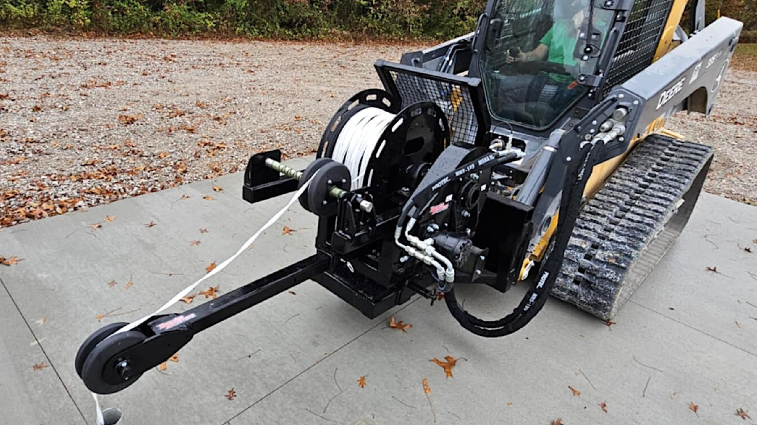
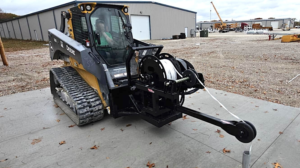
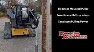
Skid steer Mounted Puller

Dimensions:
Approx. 44.5″ Wide (at Skid Steer Plate)
Approx. 51.5″ Overall Length
Drum Size:
28″ Diameter
10″ Wide between flanges
19″ Core
*Anticipated capacity = 10,000′ of 2″ Flat Strap
*Full Width lead screw level-wind to help in evenly wrapping the mule strap onto the drum
(Note: a double wrap around the lead screw roller may be required)
Lower Main Frame = 4″ x 3″ x 1/4″ wall Tubing
Upper Structure = 3″ Square Tubing
Entire Drum Rack is mounted on a HD 12″OD Slew Bearing
Rack can rotate 30 degrees in either direction, and is lockable in 15 degree increments
Drum rotates in HD Pillow Block Bearings
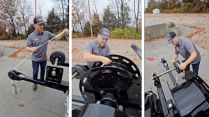
HD Hydraulic Take Up / Pay Out Assembly:
Direct Drive to Drum Shaft via Hexagonal Driver Coupling
Disengages into free-spin mode with spring loaded pull pin and slide unit
Hydraulic Drive Unit Performance:
-Available PSI = 3,500
-Available GPM = 23
470CC/rev Hydraulic Motor
5.1 Gear reduction at take-up assembly
With Strap at full drum: 225 fpm @ 23GPM / 2250 PSI – 3,000 lbs. of Line Pull
With Strap at Bare Drum: 175 fpm @ 23GPM / 1725 PSI – 3,000 lbs. of Line Pull
Double Cross Over Relief Valve to Cushion Motor on Sudden Stops and to Prevent Overload
Hydraulics are powered by the aux. tool circuit of the Skid Steer
Hydraulic Flow for Mule driver is activated via in cab switch in Skid Steer
-A system pressure control valve is included for adjusting the pulling force allowed.
-A system pressure gauge is included to monitor the pressure.
-Removable/Pinnable Jib Arm for positioning over pull pits and Switch Gear Cabinets.
Includes a 9.5″OD x 3.375W Nylatron Roller w/sealed bearings.
Extended Length = 35″ from primary departure roller
Retracted Length = 23″ from primary departure roller
Storage for jib arm included on unit
PAINT:
Unit is Completely Sandblasted
Seams are Sealed with Paintable Caulk
Rust Prohibitive Two-Part Epoxy Polyamide Primer
Two-Part Acrylic Polyurethane Topcoats – Black
All Attachments Painted before Assembly & Installed with Serviceable Fasteners